


My Part Number:
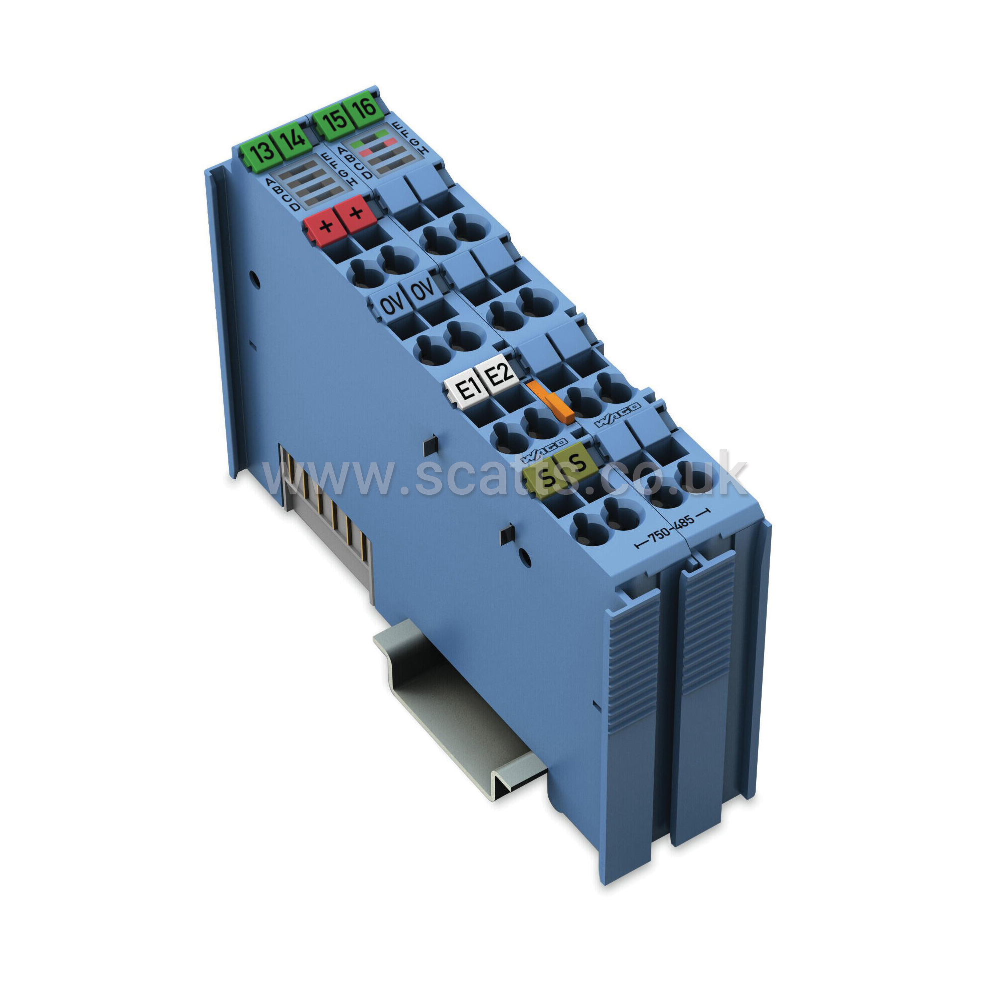
Part Number: 750-485
Manufacturer Code: 750-485
Multiples of: 1 | Minimum Order: 1
2-channel analog input - 4 - 20 m, ASingle-ended, Intrinsically safe
This analog input module powers the intrinsically safe signal conditioners located in the hazardous areas of Zone 0+1 and processes their analog signals. The WAGO I/O System 750 must be installed either in Zone 2 or in a non-hazardous area.
The 24 V supply is derived from the module's power jumper contacts. The transmitter supply is non-inherently electronically short-circuit-protected. The shield directly connects to the DIN-rail.
Indicators:
• Green LED (signal current on/off)
• Red LED (wire breakage, measurement range overflow/underflow)
Field and system levels are electrically isolated.
Number of analog inputs: 2
Total number of channels (module): 2
Signal type: Current
Signal type: 4 … 20 mADC
Sensor connection: 2 x (3-wire)
Signal characteristics: Single-ended
Resolution [bit]: 12Bit
Conversion time (typ.): 2ms
Measurement error (reference temperature): 25°C
Measurement error, deviation (max.) from the upper-range value: 0.2%
Temperature error (max.) of the upper-range value: 0.01%/K
Input resistance (max.): 100Ω
Intrinsic safety Ex i: Yes
Data width: 2 x 16-bit data; 2 x 8-bit control/status (optional)
Supply voltage (system): 5 VDC; via data contacts
Current consumption (5 V system supply): 31mA
Supply voltage (field): 24 VDC; (Ex i power supply: UO = max. 27.3 V); via power jumper contacts (power supply via blade contact; transmission via spring contact)
Current consumption, field supply (module with no external load): 11mA
Power consumption Pmax.: 1.3 W
Power loss Pl: 0.75 W
Isolation: 300 VAC system/supply
Number of incoming power jumper contacts: 2
Number of outgoing power jumper contacts: 2
Indicators: LED (A, E) green: Function AI 1, AI 2; LED (B, F) red: Error AI 1, AI 2
Marking: ATEX/IECEx: II 3 (1) G Ex ec [ia Ga] IIC T4 Gc; II (1) D [Ex ia Da] IIIC; I (M1) [Ex ia Ma] I
Brand |
WAGO |
|
£528.55
per 1 (ex. VAT)£634.26
per 1 (inc. VAT)
2-channel analog input - 4 - 20 m, ASingle-ended, Intrinsically safe
This analog input module powers the intrinsically safe signal conditioners located in the hazardous areas of Zone 0+1 and processes their analog signals. The WAGO I/O System 750 must be installed either in Zone 2 or in a non-hazardous area.
The 24 V supply is derived from the module's power jumper contacts. The transmitter supply is non-inherently electronically short-circuit-protected. The shield directly connects to the DIN-rail.
Indicators:
• Green LED (signal current on/off)
• Red LED (wire breakage, measurement range overflow/underflow)
Field and system levels are electrically isolated.
Number of analog inputs: 2
Total number of channels (module): 2
Signal type: Current
Signal type: 4 … 20 mADC
Sensor connection: 2 x (3-wire)
Signal characteristics: Single-ended
Resolution [bit]: 12Bit
Conversion time (typ.): 2ms
Measurement error (reference temperature): 25°C
Measurement error, deviation (max.) from the upper-range value: 0.2%
Temperature error (max.) of the upper-range value: 0.01%/K
Input resistance (max.): 100Ω
Intrinsic safety Ex i: Yes
Data width: 2 x 16-bit data; 2 x 8-bit control/status (optional)
Supply voltage (system): 5 VDC; via data contacts
Current consumption (5 V system supply): 31mA
Supply voltage (field): 24 VDC; (Ex i power supply: UO = max. 27.3 V); via power jumper contacts (power supply via blade contact; transmission via spring contact)
Current consumption, field supply (module with no external load): 11mA
Power consumption Pmax.: 1.3 W
Power loss Pl: 0.75 W
Isolation: 300 VAC system/supply
Number of incoming power jumper contacts: 2
Number of outgoing power jumper contacts: 2
Indicators: LED (A, E) green: Function AI 1, AI 2; LED (B, F) red: Error AI 1, AI 2
Marking: ATEX/IECEx: II 3 (1) G Ex ec [ia Ga] IIC T4 Gc; II (1) D [Ex ia Da] IIIC; I (M1) [Ex ia Ma] I
Brand |
WAGO |
|
