


My Part Number:
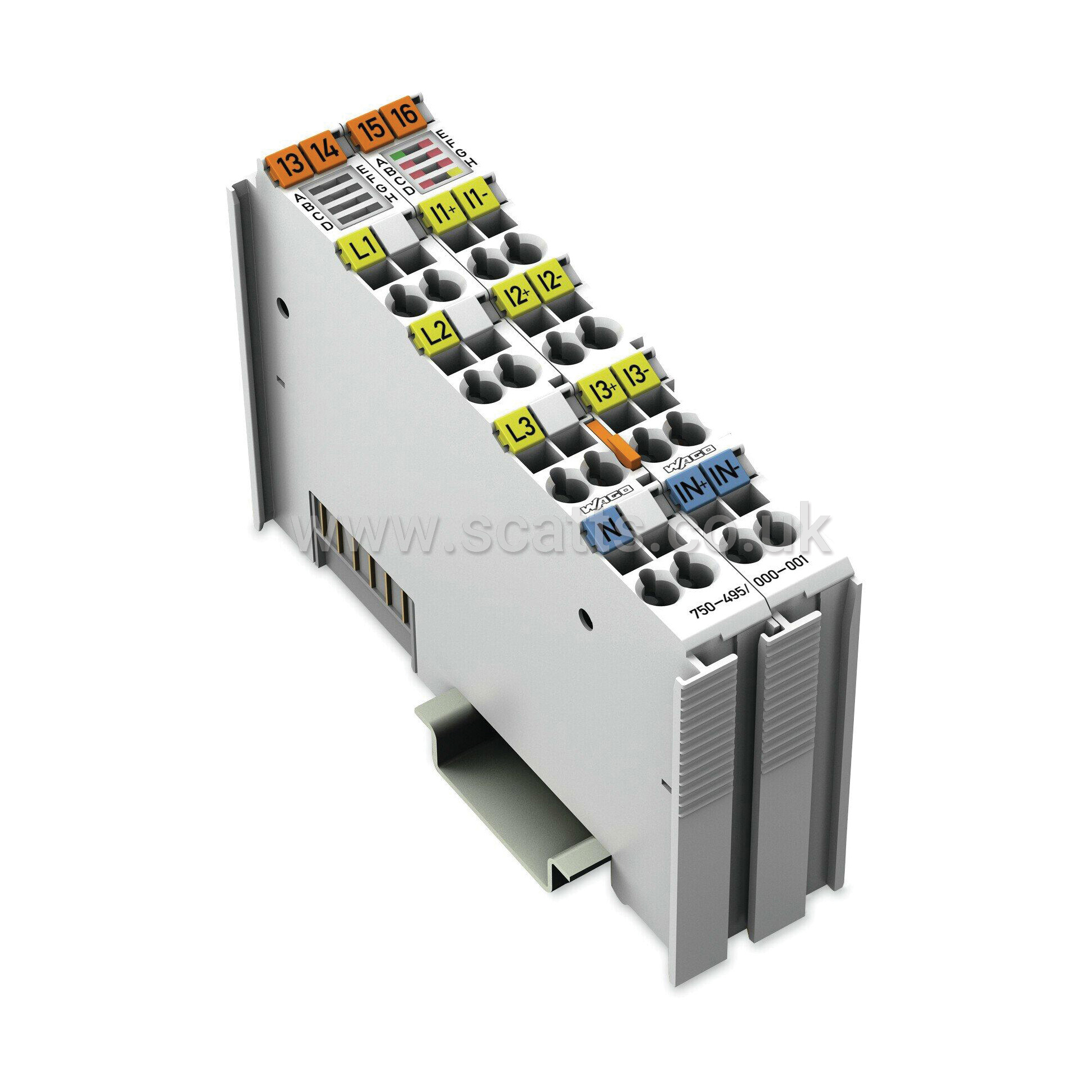
Part Number: 750-495/000-001
Manufacturer Code: 750-495/000-001
Multiples of: 1 | Minimum Order: 1
3-Phase Power Measurement - 690 VAC, 5 A
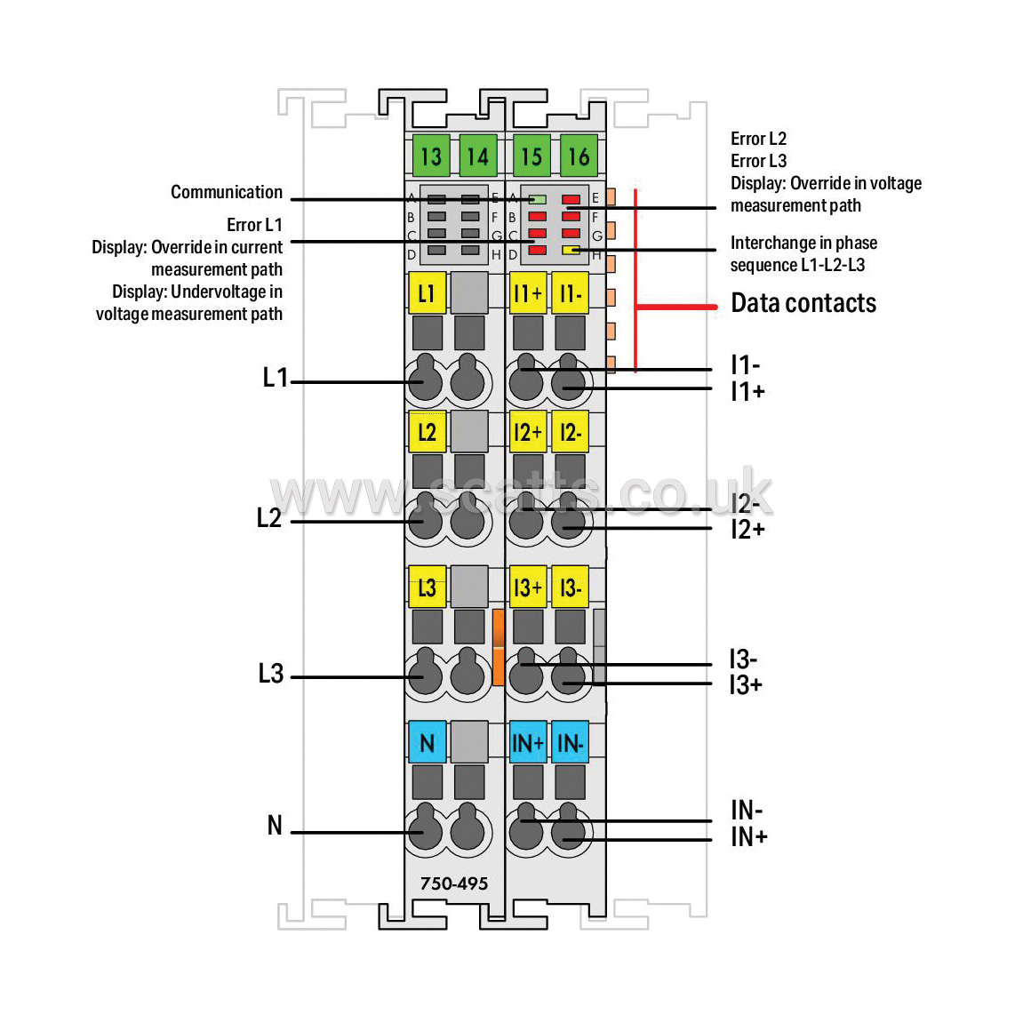
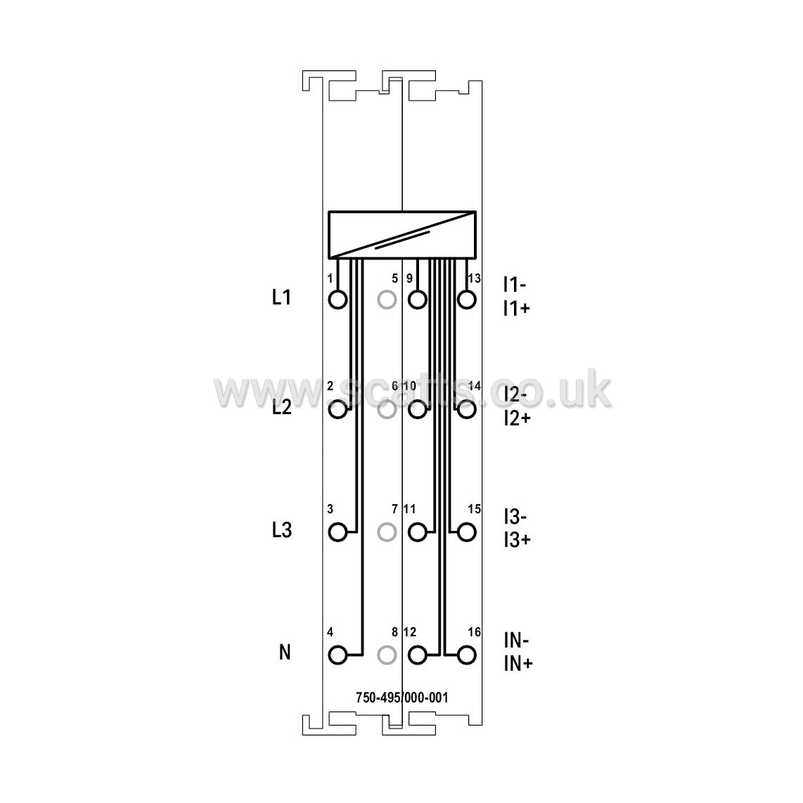
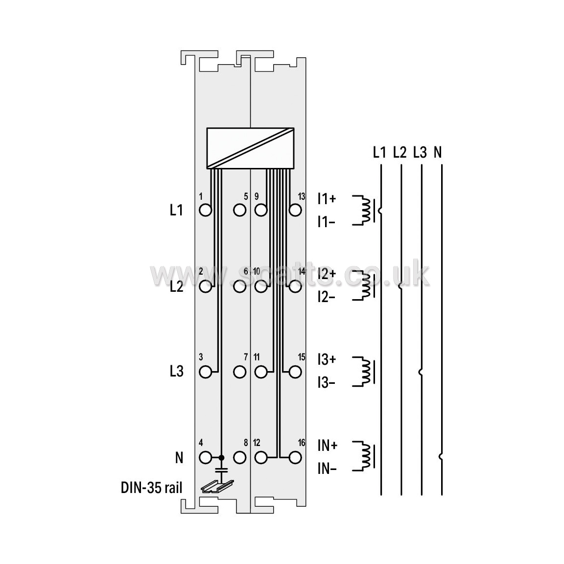
The 750-495 3-Phase Power Measurement Module measures electrical data in a three-phase supply network. The voltage is measured via network connection to L1, L2, L3 and N. The current of the three phases is fed to IL1, IL2, IL3 and IN (two clamping points each +,-) via current transformers or via Rogowski coils for the 750-495/000-002 module. The 750-495 Module transmits metrics (e.g., reactive/apparent/effective power, energy consumption, power factor, phase angle, frequency, over-/undervoltage) directly into the process image, without requiring high computing power from the controller. Both comprehensive metrics and harmonic analysis up to the 41st harmonic permit extensive network analysis via the fieldbus.
Metrics allow the operator to optimize the supply to a drive or machine, protecting the system from damage and failure. Insulation failures can be detected and prevented via current measurement performed in the neutral conductor. The 4-quadrant display indicates the type of load (inductive, capacitive) and whether it is an energy consumer or producer.
Number of measurement inputs: 7 (3 Spannungsmesseingänge, 4 differentielle Strommesseingänge)
Signal type: Power measurement
Signal form: Any periodic signals (considering the threshold frequencies)
Resolution [bit]: 24Bit
Data width: 2 x 128-bit data; 2 x 64-bit control/status
Voltage path input resistance (typ.): 1429kΩ
Current path input resistance (typ.): 5 mΩ
Reference for measurement error: AC current/voltage
Measurement error (reference temperature): 25°C
Measurement error, deviation (max.) from the upper-range value: 0.5%
Measurement current (max.): 5 A
Frequency range (mains frequency): 45 … 65 Hz
Frequency range (harmonics analysis): 0 … 3300 Hz
Limit frequency: 15.9kHz
Rated voltage: ULN = 400 V AC; ULL = 690 V AC
Calculated values: Line-to-line voltage, power output, energy, power factors, mains frequency, harmonic analysis (up to the 41st harmonic), THD
Measurement components: Evaluating
Measurement method: True RMS measurement
Configuration options: WAGO-I/O-CHECK, CODESYS Library, e!COCKPIT
Supply voltage (system): 5 VDC; via data contacts
Current consumption (5 V system supply): 100mA
Isolation: 6 kV system/field
Rated surge voltage: 6 kV
Indicators: LED (A) green: Communication; LED (B-G) red: Error L1, Override in Current Measurement Path (display), Undervoltage in Voltage Measurement Path (display), Error L2, Error L3, Override in Voltage Measurement Path (display); LED (H) yellow: Interchange in Phase Sequence L1-L2-L3
Brand |
WAGO |
|
£368.61
per 1 (ex. VAT)£442.33
per 1 (inc. VAT)
3-Phase Power Measurement - 690 VAC, 5 A
The 750-495 3-Phase Power Measurement Module measures electrical data in a three-phase supply network. The voltage is measured via network connection to L1, L2, L3 and N. The current of the three phases is fed to IL1, IL2, IL3 and IN (two clamping points each +,-) via current transformers or via Rogowski coils for the 750-495/000-002 module. The 750-495 Module transmits metrics (e.g., reactive/apparent/effective power, energy consumption, power factor, phase angle, frequency, over-/undervoltage) directly into the process image, without requiring high computing power from the controller. Both comprehensive metrics and harmonic analysis up to the 41st harmonic permit extensive network analysis via the fieldbus.
Metrics allow the operator to optimize the supply to a drive or machine, protecting the system from damage and failure. Insulation failures can be detected and prevented via current measurement performed in the neutral conductor. The 4-quadrant display indicates the type of load (inductive, capacitive) and whether it is an energy consumer or producer.
Number of measurement inputs: 7 (3 Spannungsmesseingänge, 4 differentielle Strommesseingänge)
Signal type: Power measurement
Signal form: Any periodic signals (considering the threshold frequencies)
Resolution [bit]: 24Bit
Data width: 2 x 128-bit data; 2 x 64-bit control/status
Voltage path input resistance (typ.): 1429kΩ
Current path input resistance (typ.): 5 mΩ
Reference for measurement error: AC current/voltage
Measurement error (reference temperature): 25°C
Measurement error, deviation (max.) from the upper-range value: 0.5%
Measurement current (max.): 5 A
Frequency range (mains frequency): 45 … 65 Hz
Frequency range (harmonics analysis): 0 … 3300 Hz
Limit frequency: 15.9kHz
Rated voltage: ULN = 400 V AC; ULL = 690 V AC
Calculated values: Line-to-line voltage, power output, energy, power factors, mains frequency, harmonic analysis (up to the 41st harmonic), THD
Measurement components: Evaluating
Measurement method: True RMS measurement
Configuration options: WAGO-I/O-CHECK, CODESYS Library, e!COCKPIT
Supply voltage (system): 5 VDC; via data contacts
Current consumption (5 V system supply): 100mA
Isolation: 6 kV system/field
Rated surge voltage: 6 kV
Indicators: LED (A) green: Communication; LED (B-G) red: Error L1, Override in Current Measurement Path (display), Undervoltage in Voltage Measurement Path (display), Error L2, Error L3, Override in Voltage Measurement Path (display); LED (H) yellow: Interchange in Phase Sequence L1-L2-L3
Brand |
WAGO |
|
