


My Part Number:
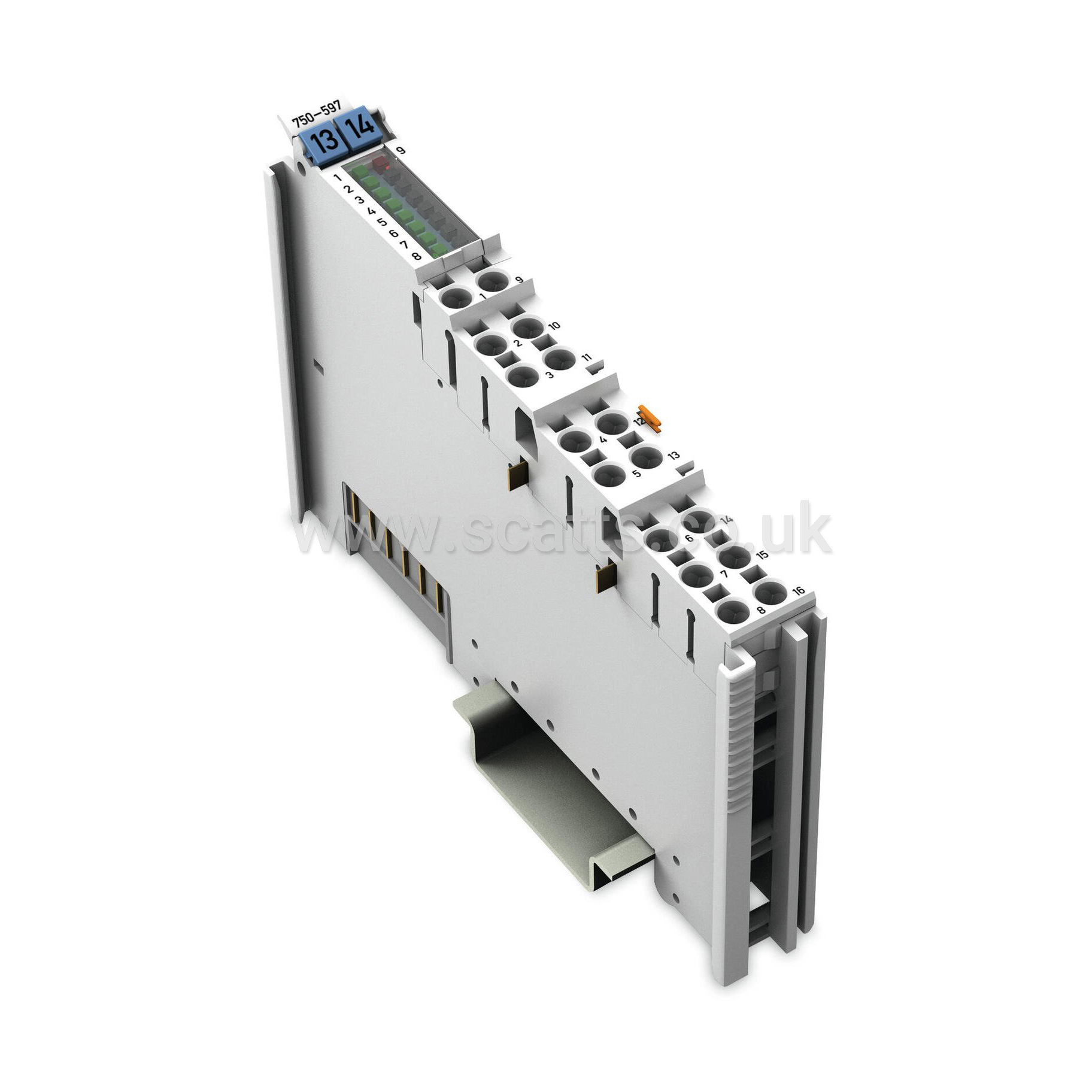
Part Number: 750-597
Manufacturer Code: 750-597
Multiples of: 1 | Minimum Order: 1
8-channel analog output - 0-10 V/±10 VDC
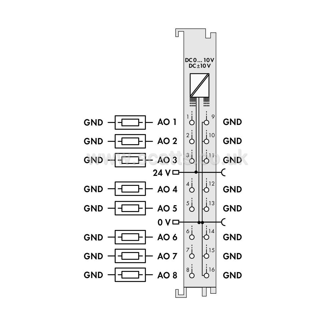
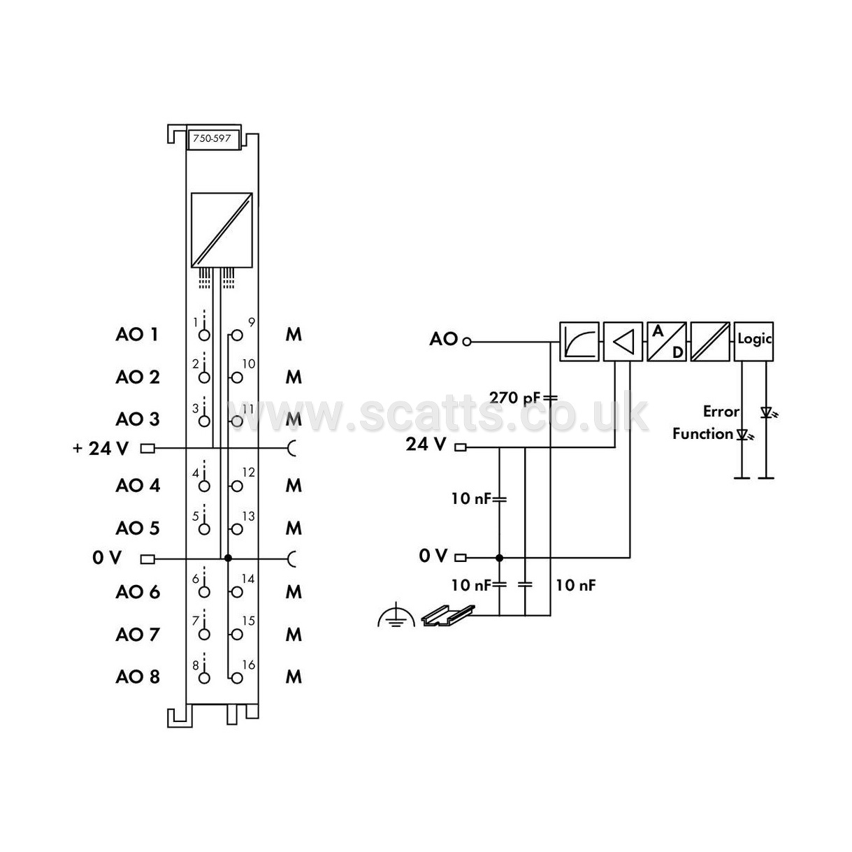
This analog output module generates signals of standard magnitudes 0-10 V and ±10 V. The output signal is electrically isolated and transmitted with a resolution of 12 bits.
Both the internal system and 24 V field side supply power the module. The module's output channels have a common ground potential. The module detects a 24 V field supply failure. The status is transmitted to the fieldbus coupler and indicated by an LED. The module can be configured via WAGO‐I/O‐CHECK or GSD files.
Number of analog outputs: 8
Total number of channels (module): 8
Signal type: Voltage
Signal type: 0 … 10 VDC
Actuator connection: 8 x (2-wire)
Resolution [bit]: 12Bit
Data width: 8 x 16-bit data; 8 x 8-bit control/status (optional)
Load impedance (voltage output): ≥ 2 kΩ
Conversion time (typ.): 13ms
Measurement error (reference temperature): 25°C
Measurement error, deviation (max.) from the upper-range value: 0.1%
Output error, deviation (max.) of the upper-range value: 0.1%
Temperature coefficient: ≤ ±10 ppm/K of the largest output area
Configuration options: WAGO-I/O-CHECK, CODESYS Library
Supply voltage (system): 5 VDC; via data contacts
Current consumption (5 V system supply): 61mA
Supply voltage (field): 24 VDC (-15 … +30 %); via power jumper contacts (power supply via blade contact; transmission via spring contact)
Isolation: 500 V system/field
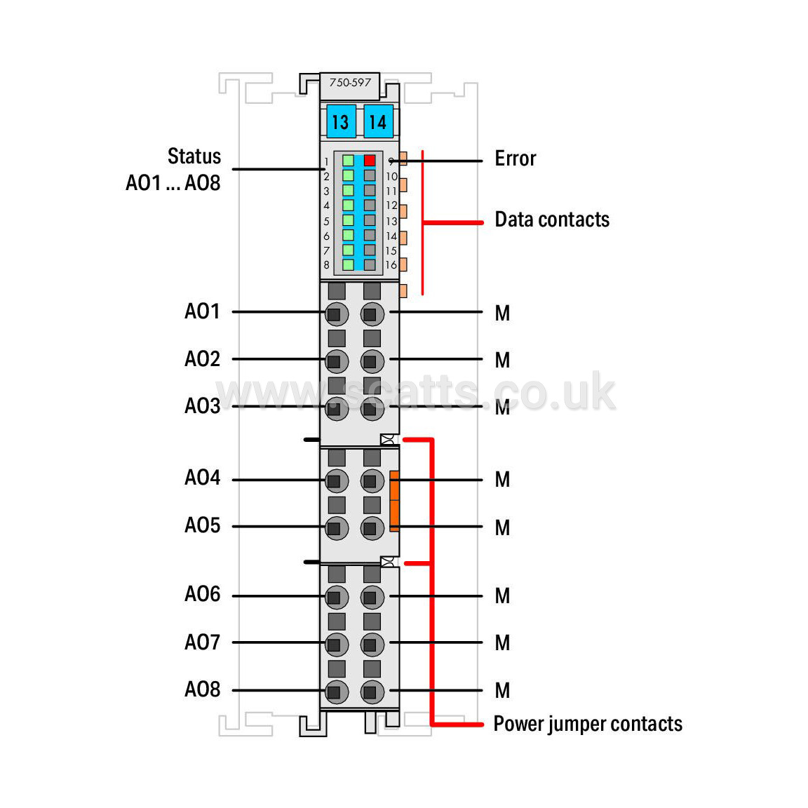
Indicators: LED (1-8) green: Status AO 1 … AO 8; LED (9) red: Error
Number of incoming power jumper contacts: 2
Number of outgoing power jumper contacts: 2
Brand |
WAGO |
|
£305.97
per 1 (ex. VAT)£367.16
per 1 (inc. VAT)
8-channel analog output - 0-10 V/±10 VDC
This analog output module generates signals of standard magnitudes 0-10 V and ±10 V. The output signal is electrically isolated and transmitted with a resolution of 12 bits.
Both the internal system and 24 V field side supply power the module. The module's output channels have a common ground potential. The module detects a 24 V field supply failure. The status is transmitted to the fieldbus coupler and indicated by an LED. The module can be configured via WAGO‐I/O‐CHECK or GSD files.
Number of analog outputs: 8
Total number of channels (module): 8
Signal type: Voltage
Signal type: 0 … 10 VDC
Actuator connection: 8 x (2-wire)
Resolution [bit]: 12Bit
Data width: 8 x 16-bit data; 8 x 8-bit control/status (optional)
Load impedance (voltage output): ≥ 2 kΩ
Conversion time (typ.): 13ms
Measurement error (reference temperature): 25°C
Measurement error, deviation (max.) from the upper-range value: 0.1%
Output error, deviation (max.) of the upper-range value: 0.1%
Temperature coefficient: ≤ ±10 ppm/K of the largest output area
Configuration options: WAGO-I/O-CHECK, CODESYS Library
Supply voltage (system): 5 VDC; via data contacts
Current consumption (5 V system supply): 61mA
Supply voltage (field): 24 VDC (-15 … +30 %); via power jumper contacts (power supply via blade contact; transmission via spring contact)
Isolation: 500 V system/field
Indicators: LED (1-8) green: Status AO 1 … AO 8; LED (9) red: Error
Number of incoming power jumper contacts: 2
Number of outgoing power jumper contacts: 2
Brand |
WAGO |
|
