


My Part Number:
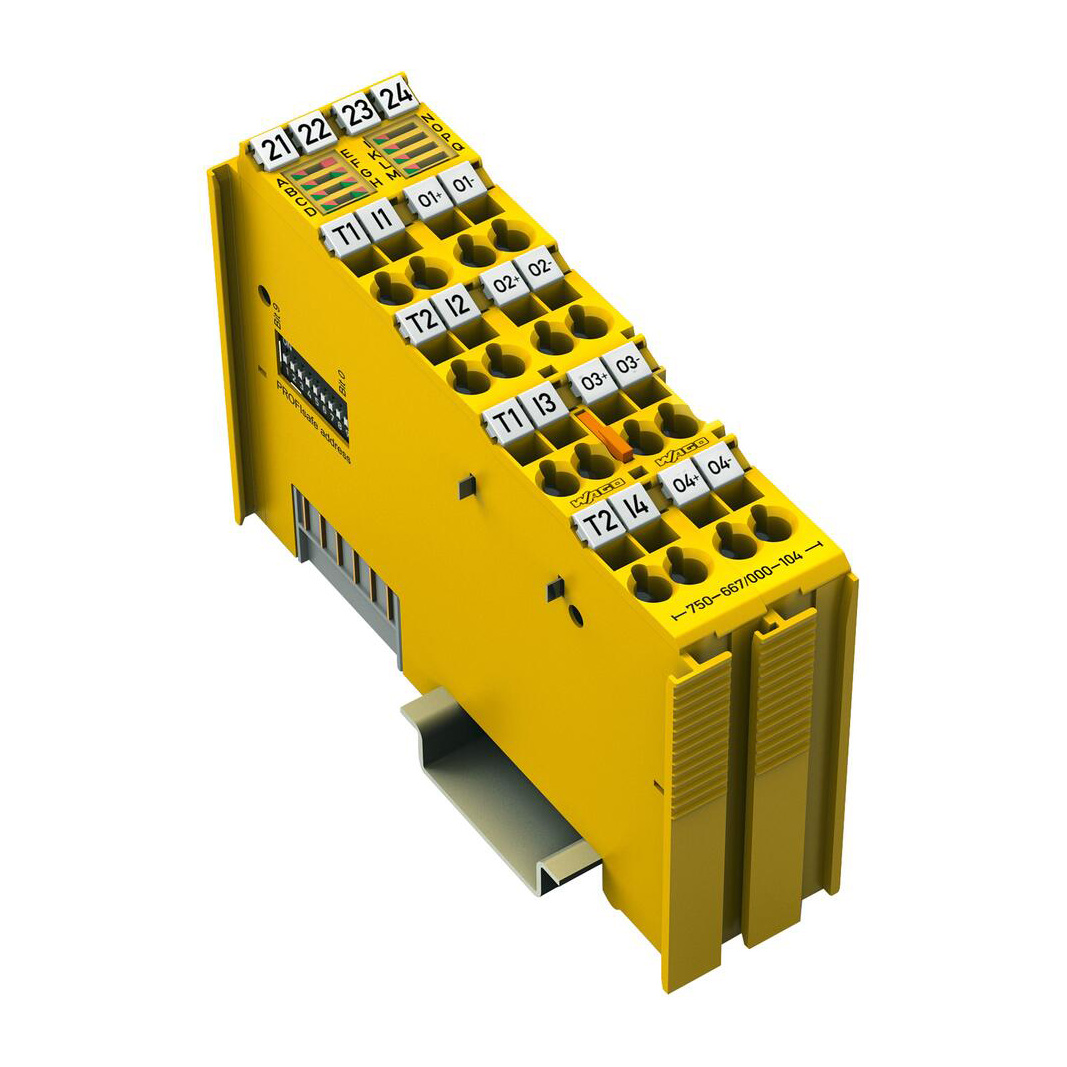
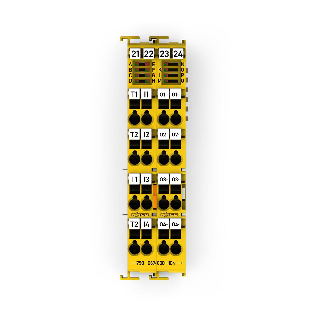
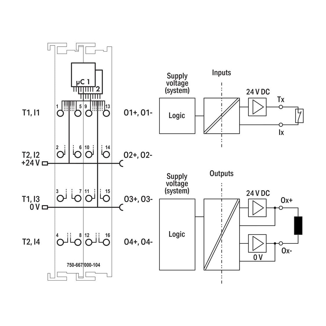
Part Number: 750-667/000-104
Manufacturer Code: 750-667/000-104
Multiples of: 1 | Minimum Order: 1
Fail-safe 4/4 channel digital input/output; 24 VDC; 2 A; Logic; PROFIsafe
General technical data
Protocols: Safe communication via PROFIsafe V2.6 (PROFINET®); Non-safe communication (PROFINET®; with functional limitations)
Configuration options: Device address adjustable via DIP switch, WAGO Safety Editor 75x or engineering software for the safety controller; Parameters adjustable via WAGO Safety Editor 75x or engineering software for the safety controller
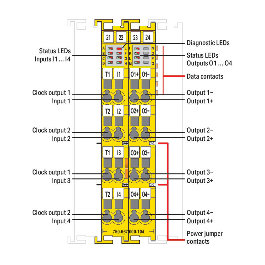
Indicators: LED (A-D) green/red: Status/error I1 … I4; LED (E) red: Module error; LED (F) red/green: Local bus communication; LED (G) red/green: Protocol status; LED (H) red/green: Parameterization; LED (I-M) red/green: Status/error O1 … O4
Device specification: GSD specfication: V2.4
Number of F I/O modules per node (fieldbus coupler/controller): See the manual for the corresponding fieldbus coupler/controller
Device-specific: Channel-granular passivation: Available; Safety logic: Up to 12 functions can be parameterized; 30 virtual inputs and outputs via process image
Pluggable connector: fixed
Digital inputs
Number of digital inputs: 4
Signal type: Digital
Signal type (voltage): 24 VDC
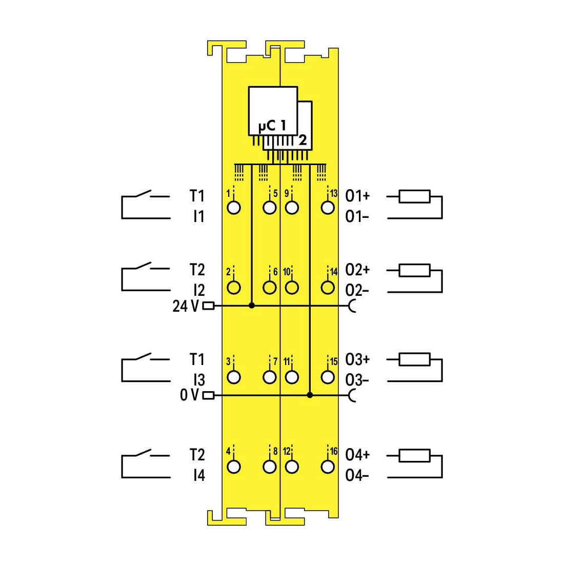
Sensor connection: 4 x (Fail-safe input with test pulse)
Input characteristic: clock sensitive
Input characteristic: Type 1 per IEC 61131
Voltage range for signal (0): −3 … +5 VDC
Voltage range for signal (1): 15 … 30 VDC
Input current per channel for signal (1) typ.: 3mA
Signal frequency (max.): 50Hz
Input filter: 0 … 200 ms (parameterizable in steps)
Response times: See product manual
Minimum signal duration: = input filter time + test pulse duration + 2 ms
Digital clock outputs
Clock outputs: 2
Signal type: Digital
Signal type (voltage): 24 VDC
Output current per channel: 0.1A
Test pulse duration (clock outputs): Between 0,5 ms and 200 ms parameterizable in steps
Connection requirement (permissible cable length): 200m
Connection requirement (permissible cable type): shielded or unshielded
Output protection (clock outputs): Short circuit and overload protection
Digital outputs
Number of digital outputs: 4
Signal type: Digital
Signal type (voltage): 24 VDC
Output characteristic: Parameterizable test pulses
Output characteristics: 2 ADC per IEC 61131-2
Output current (per channel): 2 A
Output current (module): 8A
Output residual current at signal “0”: < 1.0 mA
Output protection: Protected and short-circuit-protected per IEC 61131-2, Breaking capacity of output protection: 200 ADC, If the network supplying the power provides a short circuit current greater than the breaking capacity, then a short circuit at the output can lead to the destruction of the F I/O Module. Limitation of the inductive transient voltage: See product manual
Response threshold (output protection) min.: 2.7 ADC
Response threshold (output protection) max.: 4,4 ADC
Parallel connection of outputs: not possible
Controlling an IEC 61131‑2-compatible input: Possible; see product manual
Response times (max.) (outputs): See product manual
Switching frequency (max.): 0.1 Hz; Capacitive load (at 47 μF capacitive load and active discharge switched on)
Switching frequency (max.) (2): 0.1 Hz; Inductive load DC 13 (50 W) per IEC 60947-5-1, see product manual
Capacitive load for each channel: 47 μF
Connection requirement (permissible cable length) (2): 200m
Connection requirement (permissible cable type) (2): shielded or unshielded
Read-back time: 1 … 500 ms parameterizable in steps
Test pulse duration (digital outputs): 0 … 500 ms; test pulse duration is adaptively adjusted to the actuator and corresponds to the read-back time at most.
Response threshold (output monitoring) min.: DC 6,7 VDC (O1+ … O4+)
Response threshold (output monitoring) max.: DC 12 VDC (O1+ … O4+)
Supply voltage (system): 5 VDC; via data contacts
Current consumption (5 V system supply): 120mA
Overvoltage category: II
Supply voltage (field): 24 VDC, SELV/PELV (-25 … +20 %); via power jumper contacts (power supply via blade contact; transmission via spring contact)
Current consumption, field supply (module with no external load): 30mA
Isolation (peak value): 500 V system voltage/field level (power contacts)
Number of incoming power jumper contacts: 2
Number of outgoing power jumper contacts: 2
Current carrying capacity (power jumper contacts): 10A
Achievable safety classes: Logic: Cat. 4/PL e per ISO 13849; SIL 3 per IEC 61508 / EN 62061, Digital inputs and outputs (without clock outputs): Single-channel Cat. 2/PL d per ISO 13849-1; SIL 2 per IEC 61508 / EN 62061; dual- channel Cat. 4/PL e per ISO 13849-1; SIL 3 per IEC 61508 / EN 62061
Safety standards: IEC 61508-1 … -7; EN ISO 13849-1; EN 62061
Interface types according to ZVEI (inputs): Drain; A, C0, C1, C2, C3
Interface types according to ZVEI (outputs): Source; C0, C1, C2, C3, D0, D1, D2, D3
Connection technology: inputs/outputs: 16 x CAGE CLAMP®
Connectable conductor materials: Copper
Connection type 1: Inputs/outputs
Solid conductor: 0.08 … 2.5 mm² / 28 … 14 AWG
Fine-stranded conductor: 0.08 … 2.5 mm² / 28 … 14 AWG
Strip length: 8 … 9 mm / 0.31 … 0.35 inches
Width: 24 mm / 0.945 inches
Height: 100 mm / 3.937 inches
Depth: 67.8 mm / 2.669 inches
Depth from upper-edge of DIN-rail: 60.6 mm / 2.386 inches
Mounting type: DIN-35 rail
Pluggable connector: fixed
Housing material: Polycarbonate; polyamide 6.6
Fire load: 1.985 MJ
Weight: 101.6g
Conformity marking: EC; UKCA
Brand |
WAGO |
|
£320.00
per 1 (ex. VAT)£384.00
per 1 (inc. VAT)
Fail-safe 4/4 channel digital input/output; 24 VDC; 2 A; Logic; PROFIsafe
General technical data
Protocols: Safe communication via PROFIsafe V2.6 (PROFINET®); Non-safe communication (PROFINET®; with functional limitations)
Configuration options: Device address adjustable via DIP switch, WAGO Safety Editor 75x or engineering software for the safety controller; Parameters adjustable via WAGO Safety Editor 75x or engineering software for the safety controller
Indicators: LED (A-D) green/red: Status/error I1 … I4; LED (E) red: Module error; LED (F) red/green: Local bus communication; LED (G) red/green: Protocol status; LED (H) red/green: Parameterization; LED (I-M) red/green: Status/error O1 … O4
Device specification: GSD specfication: V2.4
Number of F I/O modules per node (fieldbus coupler/controller): See the manual for the corresponding fieldbus coupler/controller
Device-specific: Channel-granular passivation: Available; Safety logic: Up to 12 functions can be parameterized; 30 virtual inputs and outputs via process image
Pluggable connector: fixed
Digital inputs
Number of digital inputs: 4
Signal type: Digital
Signal type (voltage): 24 VDC
Sensor connection: 4 x (Fail-safe input with test pulse)
Input characteristic: clock sensitive
Input characteristic: Type 1 per IEC 61131
Voltage range for signal (0): −3 … +5 VDC
Voltage range for signal (1): 15 … 30 VDC
Input current per channel for signal (1) typ.: 3mA
Signal frequency (max.): 50Hz
Input filter: 0 … 200 ms (parameterizable in steps)
Response times: See product manual
Minimum signal duration: = input filter time + test pulse duration + 2 ms
Digital clock outputs
Clock outputs: 2
Signal type: Digital
Signal type (voltage): 24 VDC
Output current per channel: 0.1A
Test pulse duration (clock outputs): Between 0,5 ms and 200 ms parameterizable in steps
Connection requirement (permissible cable length): 200m
Connection requirement (permissible cable type): shielded or unshielded
Output protection (clock outputs): Short circuit and overload protection
Digital outputs
Number of digital outputs: 4
Signal type: Digital
Signal type (voltage): 24 VDC
Output characteristic: Parameterizable test pulses
Output characteristics: 2 ADC per IEC 61131-2
Output current (per channel): 2 A
Output current (module): 8A
Output residual current at signal “0”: < 1.0 mA
Output protection: Protected and short-circuit-protected per IEC 61131-2, Breaking capacity of output protection: 200 ADC, If the network supplying the power provides a short circuit current greater than the breaking capacity, then a short circuit at the output can lead to the destruction of the F I/O Module. Limitation of the inductive transient voltage: See product manual
Response threshold (output protection) min.: 2.7 ADC
Response threshold (output protection) max.: 4,4 ADC
Parallel connection of outputs: not possible
Controlling an IEC 61131‑2-compatible input: Possible; see product manual
Response times (max.) (outputs): See product manual
Switching frequency (max.): 0.1 Hz; Capacitive load (at 47 μF capacitive load and active discharge switched on)
Switching frequency (max.) (2): 0.1 Hz; Inductive load DC 13 (50 W) per IEC 60947-5-1, see product manual
Capacitive load for each channel: 47 μF
Connection requirement (permissible cable length) (2): 200m
Connection requirement (permissible cable type) (2): shielded or unshielded
Read-back time: 1 … 500 ms parameterizable in steps
Test pulse duration (digital outputs): 0 … 500 ms; test pulse duration is adaptively adjusted to the actuator and corresponds to the read-back time at most.
Response threshold (output monitoring) min.: DC 6,7 VDC (O1+ … O4+)
Response threshold (output monitoring) max.: DC 12 VDC (O1+ … O4+)
Supply voltage (system): 5 VDC; via data contacts
Current consumption (5 V system supply): 120mA
Overvoltage category: II
Supply voltage (field): 24 VDC, SELV/PELV (-25 … +20 %); via power jumper contacts (power supply via blade contact; transmission via spring contact)
Current consumption, field supply (module with no external load): 30mA
Isolation (peak value): 500 V system voltage/field level (power contacts)
Number of incoming power jumper contacts: 2
Number of outgoing power jumper contacts: 2
Current carrying capacity (power jumper contacts): 10A
Achievable safety classes: Logic: Cat. 4/PL e per ISO 13849; SIL 3 per IEC 61508 / EN 62061, Digital inputs and outputs (without clock outputs): Single-channel Cat. 2/PL d per ISO 13849-1; SIL 2 per IEC 61508 / EN 62061; dual- channel Cat. 4/PL e per ISO 13849-1; SIL 3 per IEC 61508 / EN 62061
Safety standards: IEC 61508-1 … -7; EN ISO 13849-1; EN 62061
Interface types according to ZVEI (inputs): Drain; A, C0, C1, C2, C3
Interface types according to ZVEI (outputs): Source; C0, C1, C2, C3, D0, D1, D2, D3
Connection technology: inputs/outputs: 16 x CAGE CLAMP®
Connectable conductor materials: Copper
Connection type 1: Inputs/outputs
Solid conductor: 0.08 … 2.5 mm² / 28 … 14 AWG
Fine-stranded conductor: 0.08 … 2.5 mm² / 28 … 14 AWG
Strip length: 8 … 9 mm / 0.31 … 0.35 inches
Width: 24 mm / 0.945 inches
Height: 100 mm / 3.937 inches
Depth: 67.8 mm / 2.669 inches
Depth from upper-edge of DIN-rail: 60.6 mm / 2.386 inches
Mounting type: DIN-35 rail
Pluggable connector: fixed
Housing material: Polycarbonate; polyamide 6.6
Fire load: 1.985 MJ
Weight: 101.6g
Conformity marking: EC; UKCA
Brand |
WAGO |
|
