


My Part Number:
Part Number: 750-338
Manufacturer Code: 750-338
Multiples of: 1 | Minimum Order: 1
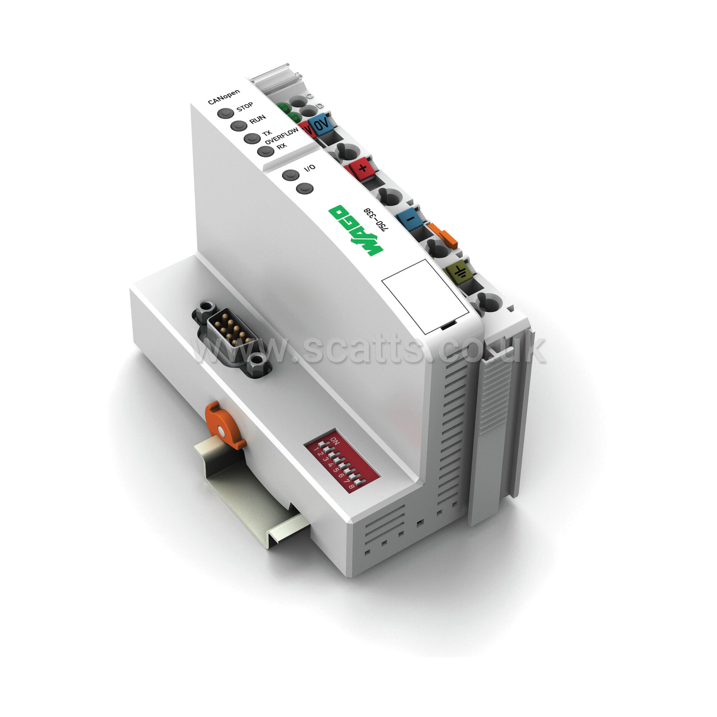
Fieldbus Coupler CANopen - D-Sub
This fieldbus coupler connects the WAGO I/O System as a slave to the CANopen fieldbus. Data is transmitted via PDOs and SDOs.
The fieldbus coupler detects all connected I/O modules and creates a local process image. Analog and specialty module data is sent via words and/or bytes, digital data is sent bit by bit.
The local process image is divided into two data zones containing the data received and the data to be sent. The process data can be sent via the CANopen bus to a control system for further processing. The process output data is sent via the CANopen bus.
The data of the analog modules is stored in the PDOs according to the order in which the modules are connected to the coupler. The bits of the digital modules are sent byte by byte and also mapped in the PDOs. If the amount of digital I/O information exceeds eight bits, the coupler automatically starts with a new byte.
All entries of the object directory can be mapped as required in the 32 Rx PDOs and 32 Tx PDOs. The complete input and output process image can be transmitted using SDOs.
Spacer modules can be set via software.
Brand |
WAGO |
|
£319.20
per 1 (ex. VAT)£383.04
per 1 (inc. VAT)
Fieldbus Coupler CANopen - D-Sub
This fieldbus coupler connects the WAGO I/O System as a slave to the CANopen fieldbus. Data is transmitted via PDOs and SDOs.
The fieldbus coupler detects all connected I/O modules and creates a local process image. Analog and specialty module data is sent via words and/or bytes, digital data is sent bit by bit.
The local process image is divided into two data zones containing the data received and the data to be sent. The process data can be sent via the CANopen bus to a control system for further processing. The process output data is sent via the CANopen bus.
The data of the analog modules is stored in the PDOs according to the order in which the modules are connected to the coupler. The bits of the digital modules are sent byte by byte and also mapped in the PDOs. If the amount of digital I/O information exceeds eight bits, the coupler automatically starts with a new byte.
All entries of the object directory can be mapped as required in the 32 Rx PDOs and 32 Tx PDOs. The complete input and output process image can be transmitted using SDOs.
Spacer modules can be set via software.
Brand |
WAGO |
|
